One of the big advantages of MPLS is that it allows for multi-tenancy, where a single underlay network can carry many different customer networks. These overlay, or customer, networks only have reachability within their own tenant. This isolation comes from route targets, which are attached when a route is exported from a VRF into BGP, and are used to control which VRFs import that route back in. VPNv4 allows routes for all customers to be distributed across the core MPLS network via a single MP-BGP session, while the underlying customer traffic itself is forwarded through the core via MPLS label switching, with the P routers remaining unaware of any VPNs.
In this lab I would like to go over the use of Route Distinguishers and Route Targets in L3 VPNs. Although a lot of these concepts transfer 1:1 to other BGP address families like EVPN VXLAN, I want to take a look at an example using MPLS. For this example we are going to build an L3 VPN so that the customer will have connectivity between their different sites and the Data Center. Then I will take a look at how we can manipulate the Route Targets to provide or remove reachability, even within a single tenant.
Let’s take a minute to define the terms and then we will take a look at how they are used.
- PE (Provider Edge) routers: hold the customers VRFs, but use one MP-BGP session (usually via a route reflector) to carry all VPNv4 routes for all VPNs at once.
- RD (Route Distinguisher): Makes overlapping customer IPs unique in that shared BGP table.
- VPNv4 Route: This is a route with the 8-byte RD attached to the IPv4 prefix.
- RT (Route Target): controls which VRF each route gets imported into.
- Label Stacking: outer label = core forwarding (P routers swap this), inner label = tells egress PE which VRF/interface to use.
Lab Topology
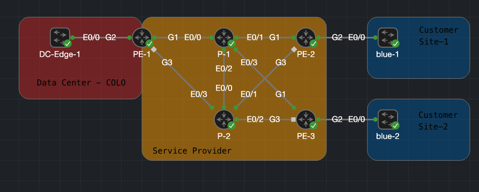
Loopbacks on Provider Routers for MP-BGP VPNv4:
- PE-1 =
10.1.255.1 - PE-2 =
10.1.255.2 - PE-3 =
10.1.255.3 - P-1 =
10.1.255.4 - P-2 =
10.1.255.5
Shared Transit Network Between Provider and Customer for BGP peering
- DC-Edge-1 to PE-1
100.65.3.0/30 - Blue1 to PE-2
100.65.1.0/30 - Blue2 to PE-3
100.65.2.0/30
Customer Networks in the VRF blue
- Site 1 Lan =
10.1.0.0/24 - Site 2 Lan =
10.0.0.0/24 - DC Lan =
192.168.200.0/24 - DC =
0.0.0.0/0
All service provider routers have reachability using OSPF so that all the Provider Loopbacks are reachable. In addition to this, MPLS LDP is enabled on all interfaces within the provider network so that labels can be created and distributed. The 2 “P” routers will only run OSPF and MPLS LDP, no further configuration is needed for these routers.
Each of the Customer switches has a LAN network noted above. In addition the DC-Edge switch is originating a default route. Normally there would be a firewall and an internet connection here, but I have not built that out.
L3VPN Configuration
Getting an L3VPN up and running has several unique steps that I am going to run through one at a time, but here is the global overview.
- Define a VRF with a unique RD and desired RTs
- Create a routed connection to the customer network and assign it to the created VRF on both sides.
- Bring up the VPNv4 MP-BGP session between the PE routers as needed.
Define the VRF and RD
Let’s create a VRF called “blue” and inside this VRF we will assign it the RD (Route Distinguisher) 123:1. This RD is very important because it makes the customer’s routes unique within the global route table by appending the RD to each route within the VPNv4 table. This allows 2 customers to use the same IP space and maintain connectivity and separation across a single MP-BGP session.
Creating a VRF on PE-1
vrf definition blue
 rd 123:1
Creating a VRF on PE-2
vrf definition blue
 rd 123:2
Creating a VRF on PE-3
vrf definition blue
 rd 123:3
Create a routed connection to the Customer
Here we will just use eBGP to exchange routes with the customer router. This will be a simple BGP session between the DC-Edge-1 switch and PE-1 router. Each PE router will have a similar configuration to the customer’s switch. Take note that on the provider edge (PE) the session is created in the VRF we created so that routes will be learned into that VRF.
PE-1 BGP configuration
router bgp 123
 address-family ipv4 vrf blue
  neighbor 100.65.3.2 remote-as 65000
  neighbor 100.65.3.2 activate
DC-Edge-1 BGP configuration
router bgp 65000
 redistribute connected
 redistribute static
 neighbor 100.65.3.1 remote-as 123
 default-information originate
Verify that BGP is up
PE-1#show bgp vpnv4 unicast vrf blue sum | b Neighbor
Neighbor        V           AS MsgRcvd MsgSent   TblVer  InQ OutQ Up/Down  State/PfxRcd
100.65.3.2      4        65000    1992    1987       15    0    0 1d06h           2
Create the VPNv4 session between the PE routers
Next we are going to bring up the MP-BGP VPNv4 sessions between all the PE routers so that all the customer sites and the DC can communicate within the VRF “blue” that we defined earlier. VPNv4 allows us to exchange VPNv4 routes, which are normal IPv4 routes with the RD attached to the route. VPNv4 is just an address family of BGP, so the configuration will look very similar. Each PE router will create a BGP session with the other 2 PE routers. I have also deactivated the address family ipv4 since it is not needed.
PE-1 VPNv4 Config
router bgp 123
 neighbor 10.1.255.2 remote-as 123
 neighbor 10.1.255.2 update-source Loopback1
 neighbor 10.1.255.3 remote-as 123
 neighbor 10.1.255.3 update-source Loopback1
 !
 address-family ipv4
  no neighbor 10.1.255.2 activate
  no neighbor 10.1.255.3 activate
 exit-address-family
 !
 address-family vpnv4
  neighbor 10.1.255.2 activate
  neighbor 10.1.255.2 send-community extended
  neighbor 10.1.255.3 activate
  neighbor 10.1.255.3 send-community extended
 exit-address-family
PE-2 VPNv4 Config
router bgp 123
 neighbor 10.1.255.1 remote-as 123
 neighbor 10.1.255.1 update-source Loopback1
 neighbor 10.1.255.3 remote-as 123
 neighbor 10.1.255.3 update-source Loopback1
 !
 address-family ipv4
  no neighbor 10.1.255.1 activate
  no neighbor 10.1.255.3 activate
 exit-address-family
 !
 address-family vpnv4
  neighbor 10.1.255.1 activate
  neighbor 10.1.255.1 send-community extended
  neighbor 10.1.255.3 activate
  neighbor 10.1.255.3 send-community extended
 exit-address-family
PE-3 VPNv4 Config
router bgp 123
 neighbor 10.1.255.1 remote-as 123
 neighbor 10.1.255.1 update-source Loopback1
 neighbor 10.1.255.2 remote-as 123
 neighbor 10.1.255.2 update-source Loopback1
 !
 address-family ipv4
  no neighbor 10.1.255.1 activate
  no neighbor 10.1.255.2 activate
 exit-address-family
 !
 address-family vpnv4
  neighbor 10.1.255.1 activate
  neighbor 10.1.255.1 send-community extended
  neighbor 10.1.255.2 activate
  neighbor 10.1.255.2 send-community extended
 exit-address-family
Verify that BGP is up and take note of the Route Distinguishers. 123:1 is going to be local to the PE-1 router that we are looking at, 123:2 is going to be PE-2, and 123:3 is going to be PE-3.
PE-1#show bgp vpnv4 unicast all | b Network
     Network          Next Hop            Metric LocPrf Weight Path
Route Distinguisher: 123:1 (default for vrf blue)
 *>i  10.0.0.0/24      10.1.255.3               0    100      0 65005 ?
 *>i  10.1.0.0/24      10.1.255.2               0    100      0 65004 ?
 *>i  100.65.1.0/30    10.1.255.2               0    100      0 65004 ?
 *>i  100.65.2.0/30    10.1.255.3               0    100      0 65005 ?
 r>   100.65.3.0/30    100.65.3.2               0             0 65000 ?
 *>   192.168.200.0    100.65.3.2               0             0 65000 ?
Route Distinguisher: 123:2
 *>i  10.1.0.0/24      10.1.255.2               0    100      0 65004 ?
 *>i  100.65.1.0/30    10.1.255.2               0    100      0 65004 ?
Route Distinguisher: 123:3
 *>i  10.0.0.0/24      10.1.255.3               0    100      0 65005 ?
 *>i  100.65.2.0/30    10.1.255.3               0    100      0 65005 ?
Using Route Targets
Let’s take a look at Route Targets and how I’m using them to control which routes get learned within each customer tenant. As noted above, Route Targets control which VRF a route gets imported into. Each VRF can define one or more export route targets, which get attached to the route as an extended community when it’s redistributed into VPNv4. For reachability to work, a receiving VRF must be configured to import that same route target — if the export and import RTs don’t match, the route simply won’t be pulled in.
For this example I want both of the customer sites to be able to communicate with the DC network and use the default route, but I do not want Site-1 and Site-2 to be able to talk to each other. Let’s take a look at the RTs I have defined and how that is accomplished.
PE-1 Route Targets Connected to DC-Edge-1
vrf definition blue
 address-family ipv4
  route-target export 123:4002
  route-target import 123:4000
  route-target import 123:4001
PE-2 Route Targets Connected to blue-1
vrf definition blue
 address-family ipv4
  route-target export 123:4000
  route-target import 123:4002
PE-3 Route Targets Connected to blue-2
vrf definition blue
 address-family ipv4
  route-target export 123:4001
  route-target import 123:4002
As you can see, PE-1 is importing both route targets from the customer sites so it will have reachability to these sites. PE-2 and PE-3 only import the route target from PE-1, so they will only be able to reach the DC networks.
Just to confirm, let’s take a look at the BGP table from blue-1. We should only see the 2 DC routes learned via BGP and not the LAN network of blue-2 10.0.0.0/24.
blue-1#show ip route | b Gateway
Gateway of last resort is 100.65.1.1 to network 0.0.0.0

B*    0.0.0.0/0 [20/0] via 100.65.1.1, 00:26:43
      10.0.0.0/8 is variably subnetted, 2 subnets, 2 masks
C        10.1.0.0/24 is directly connected, Vlan500
L        10.1.0.1/32 is directly connected, Vlan500
      100.0.0.0/8 is variably subnetted, 3 subnets, 2 masks
C        100.65.1.0/30 is directly connected, Vlan100
L        100.65.1.2/32 is directly connected, Vlan100
B        100.65.3.0/30 [20/0] via 100.65.1.1, 17:23:00
B     192.168.200.0/24 [20/0] via 100.65.1.1, 17:23:00
This looks good!
Download
Here is the CML lab file to try it out for yourself.