VPLS (Virtual Private LAN Service), also called E-LAN, is a multipoint L2VPN, it emulates a single switched Ethernet LAN across multiple PE routers. Under the hood this is built from a full mesh of pseudowires between the PEs, but unlike an L3VPN, MAC learning is done entirely in the data plane, the same way a traditional switch learns MAC addresses off a wire. Since there’s no Spanning Tree running across the MPLS core, split-horizon is used between the pseudowires instead to keep the full mesh from looping traffic back on itself.
One thing worth calling out up front: once a provider turns up VPLS, they are now participating in MAC address learning on behalf of the customer. Because of this, providers will typically cap the number of MAC addresses a PE will learn per VPLS instance, so a misbehaving or compromised customer device can’t flood the PE’s MAC table.
In this lab I want to build a VPLS instance that stretches a single Ethernet segment across three PE routers, using BGP for both autodiscovery of the other PEs and signaling of the pseudowires themselves, instead of relying on LDP.
Let’s take a minute to define the terms and then take a look at how they’re used.
- VFI (Virtual Forwarding Instance): Defines the configuration and membership of the core pseudowires in the VPLS. A VFI is a virtual Layer 2 bridge that connects attachment circuits which are physical Ethernet ports, logical Ethernet ports, or pseudowires from CE devices to the virtual circuits that make up the VPLS mesh.
- Bridge Domain: An object that represents a Layer 2 broadcast domain on a device.
- EVC (Ethernet Virtual Circuit): A port-level point-to-point or multipoint-to-multipoint Layer 2 circuit.
- EFP (Ethernet Flow Point): An instance of an Ethernet flow on a particular interface that belongs to a bridge domain.
- VPLS Signaling: Can be done with either LDP or BGP. The advantage of BGP is autodiscovery — PEs learn about each other automatically instead of every pseudowire being manually configured on every PE.
- VPN ID: Used to derive the RD and RT that determine VFI membership.
- VE ID: Only needed when using BGP signaling. A unique ID to identify an endpoint within the VPLS domain.
Lab Topology
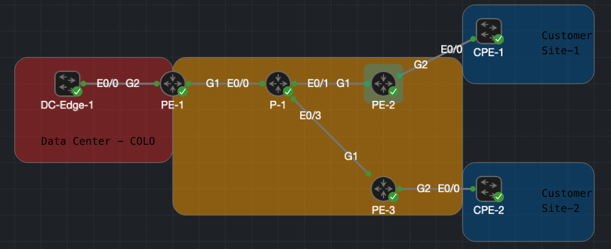
Loopbacks on Provider Routers for OSPF/MPLS LDP:
- PE-1 =
10.1.255.1 - PE-2 =
10.1.255.2 - PE-3 =
10.1.255.3 - P-1 =
10.1.255.4
Core links between P-1 and the PE routers, running OSPF and MPLS LDP:
- P-1 to PE-1
10.1.1.0/30 - P-1 to PE-2
10.1.1.4/30 - P-1 to PE-3
10.1.1.8/30
Customer AC (attachment circuits) into the VPLS bridge domain:
- DC-Edge-1 to PE-1 - vlan 100
- CPE-1 to PE-2 - vlan 100
- CPE-2 to PE-3 - vlan 68
Customer LAN, stretched flat across all three sites as a single VPLS bridge domain, each of the customer router have an interface on on the 100.1.1.0/24 subnet.
All service provider routers have reachability using OSPF so that the PE loopbacks are reachable, and MPLS LDP is enabled on every core-facing interface so labels can be built and distributed. P-1 only runs OSPF and MPLS LDP as a P router.
Notice that CPE-2 connects to PE-3 tagged as VLAN 68, while DC-Edge-1 and CPE-1 use VLAN 100 on their respective links. Each site is free to use its own local VLAN tag because the PE pops that tag at the edge before the frame ever enters the VPLS bridge domain, the customer sites don’t need matching VLAN numbers, only IP addressing in the same subnet, to be part of the same flat L2 segment.
VPLS Configuration
Bringing up VPLS with BGP autodiscovery and signaling breaks down into a few steps, here’s the overview before digging into each one.
- Define a VFI with a VPN ID and enable BGP autodiscovery and signaling.
- Build the attachment circuit toward the customer (the EFP) and bind it, along with the VFI, into a bridge domain.
- Enable the
l2vpn vplsaddress-family under BGP so the PEs can discover each other and exchange pseudowire labels.
Define the VFI
Each PE gets a VFI called vpls1, tied together by a shared VPN ID of 100. The VPN ID is what’s used to derive the RD and RT behind the scenes, which is why there’s no explicit route-target statement needed under the VFI here — that’s also possible to configure explicitly if you want tighter control over import/export policy, but for this lab I’m letting it be derived automatically from the VPN ID.
The ve id uniquely identifies each PE within the VPLS instance and is only needed because we’re using BGP for signaling. ve range tells the PE how many VE IDs to expect across the instance.
PE-1
l2vpn vfi context vpls1
 vpn id 100
 autodiscovery bgp signaling bgp
  ve id 1001
  ve range 12
PE-2
l2vpn vfi context vpls1
 vpn id 100
 autodiscovery bgp signaling bgp
  ve id 1002
  ve range 12
PE-3
l2vpn vfi context vpls1
 vpn id 100
 autodiscovery bgp signaling bgp
  ve id 1003
  ve range 12
Worth noting: autodiscovery bgp signaling bgp is doing two jobs at once. The autodiscovery bgp part means BGP is used to find the other PE members of this VPLS instance, and signaling bgp means BGP is also used to exchange the actual pseudowire labels. If I dropped signaling bgp and left just autodiscovery bgp, the PEs would still find each other via BGP, but would fall back to LDP.
Build the Attachment Circuit and Bridge Domain
On the customer-facing interface, a service instance (EFP) classifies the incoming 802.1Q tagged traffic and pops the tag before it’s handed off into the bridge domain. The bridge domain is then the glue that ties the attachment circuit to the VFI.
PE-1
interface GigabitEthernet2
 no ip address
 service instance 100 ethernet
  encapsulation dot1q 100
  rewrite ingress tag pop 1 symmetric
!
bridge-domain 100
 member GigabitEthernet2 service-instance 100
 member vfi vpls1
PE-2
interface GigabitEthernet2
 no ip address
 service instance 100 ethernet
  encapsulation dot1q 100
  rewrite ingress tag pop 1 symmetric
!
bridge-domain 100
 member GigabitEthernet2 service-instance 100
 member vfi vpls1
PE-3
interface GigabitEthernet2
 no ip address
 service instance 100 ethernet
  encapsulation dot1q 68
  rewrite ingress tag pop 1 symmetric
!
bridge-domain 100
 member GigabitEthernet2 service-instance 100
 member vfi vpls1
Note that PE-3’s service instance is still numbered 100 locally (that number is just a local identifier on the interface), but it’s matching on dot1q 68 coming from CPE-2. The rewrite ingress tag pop 1 symmetric strips that tag on the way in and re-applies it symmetrically on the way out, which is what lets CPE-2 use a different VLAN number than DC-Edge-1 and CPE-1 while still landing in the same bridge domain.
Bring Up the l2vpn vpls Address-Family
Last step is a standard iBGP full mesh between the PE loopbacks, with the l2vpn vpls address-family activated. suppress-signaling-protocol ldp under the address-family is the other half of what I mentioned above it tells this PE not to fall back to LDP for signaling with a given neighbor, keeping everything on BGP.
PE-1
router bgp 65000
 no bgp default ipv4-unicast
 neighbor 10.1.255.2 remote-as 65000
 neighbor 10.1.255.2 update-source Loopback1
 neighbor 10.1.255.3 remote-as 65000
 neighbor 10.1.255.3 update-source Loopback1
 !
 address-family l2vpn vpls
  neighbor 10.1.255.2 activate
  neighbor 10.1.255.2 send-community extended
  neighbor 10.1.255.2 suppress-signaling-protocol ldp
  neighbor 10.1.255.3 activate
  neighbor 10.1.255.3 send-community extended
  neighbor 10.1.255.3 suppress-signaling-protocol ldp
 exit-address-family
PE-2
router bgp 65000
 no bgp default ipv4-unicast
 neighbor 10.1.255.1 remote-as 65000
 neighbor 10.1.255.1 update-source Loopback1
 neighbor 10.1.255.3 remote-as 65000
 neighbor 10.1.255.3 update-source Loopback1
 !
 address-family l2vpn vpls
  neighbor 10.1.255.1 activate
  neighbor 10.1.255.1 send-community extended
  neighbor 10.1.255.1 suppress-signaling-protocol ldp
  neighbor 10.1.255.3 activate
  neighbor 10.1.255.3 send-community extended
  neighbor 10.1.255.3 suppress-signaling-protocol ldp
 exit-address-family
PE-3
router bgp 65000
 no bgp default ipv4-unicast
 neighbor 10.1.255.1 remote-as 65000
 neighbor 10.1.255.1 update-source Loopback1
 neighbor 10.1.255.2 remote-as 65000
 neighbor 10.1.255.2 update-source Loopback1
 !
 address-family l2vpn vpls
  neighbor 10.1.255.1 activate
  neighbor 10.1.255.1 send-community extended
  neighbor 10.1.255.1 suppress-signaling-protocol ldp
  neighbor 10.1.255.2 activate
  neighbor 10.1.255.2 send-community extended
  neighbor 10.1.255.2 suppress-signaling-protocol ldp
 exit-address-family
Verification
Verify the Circuits are up:
PE-2#show mpls l2transport vc

Local intf     Local circuit              Dest address    VC ID      Status
-------------  -------------------------- --------------- ---------- ----------
VFI vpls1      vfi                        10.1.255.1      100        UP
VFI vpls1      vfi                        10.1.255.3      100        UP
To see the pseudowire labels in a BGP-signaled VPLS, you need two commands one for the service (inner) label, one for the transport (outer) label.
Service label — show l2vpn vfi vpls1
PE-2#show l2vpn vfi
VFI name: vpls1, state: up, type: multipoint, signaling: BGP
  VPN ID: 100, VE-ID: 1002, VE-SIZE: 12
  RD: 65000:100, RT: 65000:100
  Interface          Peer Address    VE-ID  Local Label  Remote Label    S
  pseudowire100003   10.1.255.3      1003   23           22              Y
  pseudowire100002   10.1.255.1      1001   21           22              Y
Local Label is what this PE told each peer to use when sending traffic to it; Remote Label is what each peer told this PE to use in the other direction. These are the innermost label on any VPLS frame — the one that tells the receiving PE which bridge domain to hand the frame to.
Transport label — show mpls forwarding-table
PE-2#show mpls forwarding-table
Local      Outgoing   Prefix           Bytes Label   Outgoing   Next Hop
Label      Label      or Tunnel Id     Switched      interface
16         No Label   lbl-blk-id(1:0)  0             drop
17         No Label   lbl-blk-id(1:1)  0             drop
18         No Label   lbl-blk-id(1:2)  0             drop
19         No Label   lbl-blk-id(1:3)  0             drop
20         No Label   lbl-blk-id(1:4)  0             drop
21         No Label   lbl-blk-id(1:5)  2022          none       point2point
22         No Label   lbl-blk-id(1:6)  0             drop
23         No Label   lbl-blk-id(1:7)  390           none       point2point
24         No Label   lbl-blk-id(1:8)  0             drop
25         No Label   lbl-blk-id(1:9)  0             drop
26         No Label   lbl-blk-id(1:10) 0             drop
27         No Label   lbl-blk-id(1:11) 0             drop
28         Pop Label  10.1.1.0/30      0             Gi1        10.1.1.5
29         Pop Label  10.1.1.8/30      0             Gi1        10.1.1.5
30         17         10.1.255.1/32    0             Gi1        10.1.1.5
31         18         10.1.255.3/32    0             Gi1        10.1.1.5
32         Pop Label  10.1.255.4/32    0             Gi1        10.1.1.5
The lbl-blk-id rows are the 12-label block (matching VE-SIZE 12) PE-2 carved out and advertised via BGP autodiscovery. Only two slots are active — 21 and 23 — matching the Local Labels above; the rest are unused reserved slots (drop). These entries have no real outgoing interface because popping them hands the frame into the bridge domain rather than back into MPLS forwarding.
The outer label lives under the peer’s loopback prefix in the same table: reaching PE-1 (10.1.255.1/32) uses outgoing label 17, reaching PE-3 (10.1.255.3/32) uses outgoing label 18.
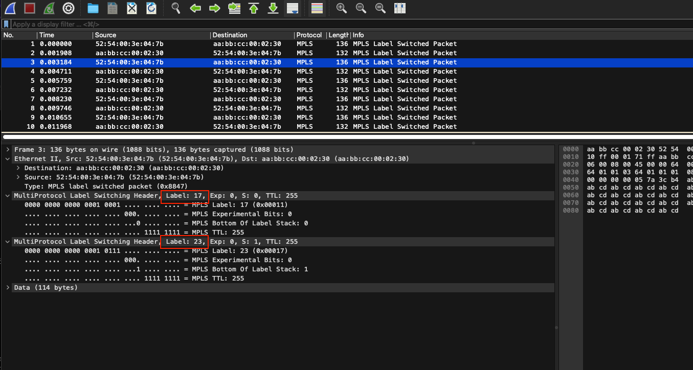
Put together, a frame PE-2 sends toward PE-1 carries the stack [17, 23] 17 the Transport Label is swapped/popped hop-by-hop by LDP across the core, 23 is what’s left once it reaches PE-1 and tells it which VFI to bridge the frame into. As you can see from the Packet Capture of a ping below, we have both of those headers.