Sysmmetric Irb Anycast Gateway On Catalyst
Symmetric IRB with an Anycast Gateway using VXLAN EVPN
In this post, we walk through a practical configuration of Symmetric Integrated Routing and Bridging (IRB) using an Anycast Gateway in a VXLAN EVPN fabric. If you are new to IRB, I previously covered the forwarding mechanics in detail here, so this article focuses primarily on implementation.
Symmetric IRB allows hosts to use the same default gateway IP and MAC address regardless of which leaf switch they are connected to, while still enabling inter-subnet routing across the fabric. To accomplish this, we introduce a Transit VNI (L3 VNI) that carries routed traffic between VTEPs.
In this lab, we configure both:
- an L3 VNI for symmetric IRB routing
- an L2 VNI for traditional bridged connectivity
This demonstrates how Layer 2 and Layer 3 VXLAN services can coexist on the same VTEP.
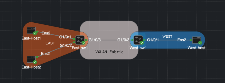
Lab Topology
This is a very simple topology consisting of two switches and several attached hosts. IRB can become complex quickly, so starting with a minimal design helps build a solid understanding of the control-plane behavior.
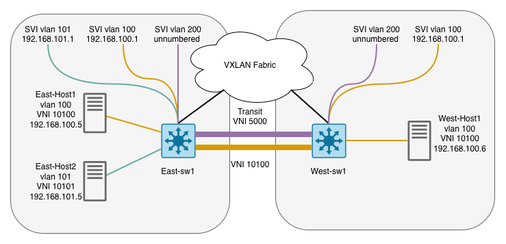
Two Catalyst switches form a VXLAN EVPN fabric. Each switch has a loopback interface used as the EVPN router-id, VTEP source interface, and addressing for VLAN 200. OSPF provides reachability between loopbacks in the underlay network.
VLAN 200 acts as the L3 transit segment enabling symmetric IRB. VLAN 100 is configured as an Anycast gateway on both switches, sharing the same IP address and the same virtual MAC address.
- WEST-sw1:
- Lo1:
10.0.255.201 - VLAN 200:
10.0.255.201— VNI 5000 (L3 Transit) - VLAN 100:
192.168.100.1— VNI 10100
- Lo1:
- EAST-sw1:
- Lo1:
10.0.255.200 - VLAN 200:
10.0.255.200— VNI 5000 (L3 Transit) - VLAN 100:
192.168.100.1— VNI 10100 - VLAN 101:
192.168.101.1— VNI 10101
- Lo1:
- East-Host1:
192.168.100.5— VLAN 100 - East-Host2:
192.168.101.5— VLAN 101 - West-Host1:
192.168.100.6— VLAN 100
OSPF Underlay
The underlay network is responsible for providing IP reachability between VTEPs. In this example, OSPF is used to advertise loopback interfaces between the two switches.
Each switch uses Loopback1 as:
- BGP router-id
- EVPN peering source
- L3 transit addressing reference for VLAN 200
interface Loopback1
 ip address 10.0.255.200 255.255.255.255

interface GigabitEthernet1/0/3
 no switchport
 ip address 10.0.255.1 255.255.255.252
 ip ospf network point-to-point

router ospf 1
 router-id 10.0.255.200
 network 10.0.255.0 0.0.0.255 area 0
VRF Definition
VRFs are used to separate tenant routing information from the global routing table. They become especially important in a VXLAN fabric when segmentation or multi-tenancy is required. Let’s quickly go over the function of RDs, Route Targets, and Stitching.
Route Distinguisher (RD)
The Route Distinguisher ensures routes inside the VRF remain unique when advertised via MP-BGP. Without an RD, two VTEPs advertising the same prefix (e.g., 192.168.100.0/24) would be indistinguishable in the BGP table.
Route Targets
Route targets control import/export policy between VTEPs. In this example, EAST-sw1 exports routes tagged with 103:2 and only imports routes tagged with 104:2. This means WEST-sw1 must export its routes with 104:2 for EAST-sw1 to accept them, and vice versa. This asymmetric design gives you granular control over which routing information is shared between tenants or between different parts of the fabric.
Route Target Stitching
Stitching allows L3 routes to be properly exchanged between VRFs using EVPN Type-5 routes. This is essential for the L3 VXLAN transit to work. In this design, VLAN 100 and VLAN 101 will be advertised as Type-5 routes.
vrf definition north
 rd 103:65001
 !
 address-family ipv4
  route-target export 103:2
  route-target import 104:2
  route-target export 103:2 stitching
  route-target import 104:2 stitching
 exit-address-family
MP-BGP EVPN
Next we bring up MP-BGP EVPN. We enable both global EVPN and VRF-specific route exchange.
router bgp 65001
 bgp log-neighbor-changes
 no bgp default ipv4-unicast
 neighbor 10.0.255.201 remote-as 65001
 neighbor 10.0.255.201 update-source Loopback1
 !
 address-family ipv4
 exit-address-family
 !
 address-family l2vpn evpn
  neighbor 10.0.255.201 activate
  neighbor 10.0.255.201 send-community both
 exit-address-family
 !
 address-family ipv4 vrf north
  advertise l2vpn evpn
  redistribute connected
 exit-address-family
Enable L2VPN EVPN
We introduce a key command here: default-gateway advertise. This ensures the Anycast gateway MAC and IP are advertised via EVPN Type-2 routes. Without this command, remote VTEPs would learn host MAC/IP bindings but would not learn the Anycast gateway information, preventing hosts from using the local VTEP as their default gateway.
l2vpn evpn
 router-id Loopback1
 default-gateway advertise
Next, we map VLANs to VNIs. It is important to understand the difference between the configuration of VLAN 100 and VLAN 200.
VLAN 100 is configured as a traditional Layer 2 segment and is associated with an EVPN instance. This tells the switch that MAC address learning and host reachability information for this VLAN should be advertised using EVPN.
VLAN 200, however, is not associated with an EVPN instance. Instead, it is mapped directly to a VNI that acts as the Layer 3 transit VNI used for symmetric IRB routing. Although VLAN 200 is still technically a VLAN, in this design it represents the L3 VNI that interconnects routing tables between VTEPs rather than a user-facing broadcast domain.
This distinction can feel unintuitive at first because both segments are configured under VLAN configuration, yet they serve very different roles in the VXLAN fabric.
l2vpn evpn instance 1 vlan-based
 encapsulation vxlan

vlan configuration 100
 member evpn-instance 1 vni 10100

vlan configuration 200
 member vni 5000
Configure NVE Interface
The NVE interface provides VXLAN encapsulation and uses BGP EVPN for control-plane learning. The only addition compared to a basic L2 VXLAN configuration is the L3 VNI bound to VRF north.
Note: The
source-interfacemust match the loopback used for OSPF and BGP peering —Loopback1in this lab.
interface nve1
 no ip address
 source-interface Loopback1
 host-reachability protocol bgp
 member vni 10100 ingress-replication
 member vni 10101 ingress-replication
 member vni 5000 vrf north
SVIs
Anycast Gateway SVI
Both switches share the same IP address and the same virtual MAC address. Configuring a static MAC ensures that hosts see a consistent gateway MAC regardless of which VTEP they are connected to. Without a shared MAC, ARP responses from different VTEPs would carry different source MACs, causing traffic to be sent to the wrong VTEP after a host moves.
Because EVPN advertises the gateway MAC/IP combination via Type-2 routes, remote VTEPs learn the gateway binding and can forward traffic correctly.
interface Vlan100
 vrf forwarding north
 ip address 192.168.100.1 255.255.255.0
 mac-address <anycast-mac>
L3 Transit SVI
This is our transit VLAN, mapped to VNI 5000. It is used internally for symmetric routing between VTEPs and is not a user-facing segment. Using ip unnumbered Loopback1 avoids allocating a separate subnet for this transit link. no autostate ensures the SVI stays up even when no access ports are active in VLAN 200.
interface Vlan200
 description CORE-SVI L3
 vrf forwarding north
 ip unnumbered Loopback1
 no autostate
Traffic Flow: Symmetric IRB
To make the control-plane behavior concrete, here is what happens when West-Host1 (192.168.100.6) sends traffic to East-Host2 (192.168.101.5):
- West-Host1 ARPs for its default gateway (
192.168.100.1). WEST-sw1 responds with the Anycast gateway MAC. - West-Host1 sends the frame to West-sw1. West-sw1 recognizes the destination IP is in a different subnet and routes the packet within VRF
north. - West-sw1 looks up
192.168.101.0/24in VRFnorth. It was learned as a Type-5 route from East-sw1 via MP-BGP EVPN. - West-sw1 encapsulates the packet in VXLAN using the L3 VNI (5000) and sends it to East-sw1’s VTEP IP.
- East-sw1 decapsulates the packet, looks up the destination in VRF
north, and forwards it out the VLAN 101 SVI to East-Host2.
The return path is symmetric: EAST-sw1 encapsulates return traffic using VNI 5000 back to WEST-sw1. This is what distinguishes symmetric IRB from asymmetric IRB — both directions use the L3 VNI, so each VTEP only needs to hold the routes for its own local subnets plus whatever is advertised via BGP.
verify
Here are a couple of show commands to verify that everything is up and work, lastly dont forget to do those ping test!
show nve peers: This command verifies that VXLAN tunnel endpoints (VTEPs) have successfully formed adjacencies. Notice that we see both an L2 VNI peer and an L3 VNI peer, confirming that both bridging and routing VNIs are operational.
East-SW1#show nve peers
'M' - MAC entry download flag  'A' - Adjacency download flag
'4' - IPv4 flag  '6' - IPv6 flag

Interface  VNI      Type Peer-IP          RMAC/Num_RTs   eVNI     state flags UP time
nve1       5000     L3CP 10.0.255.201     5254.000d.cc73 5000       UP  A/M/4 05:07:46
nve1       10100    L2CP 10.0.255.201     7              10100      UP   N/A  1d04h
**show l2vpn evpn peers vxlan **
East-SW1#show l2vpn evpn peers vxlan

Interface VNI      Peer-IP                                 Num routes eVNI     UP time
--------- -------- --------------------------------------- ---------- -------- --------
nve1      10100    10.0.255.201                            7          10100    1d04h
show l2vpn evpn evi 1 detail This is one of the most useful verification commands because it shows how the L2 and L3 VNIs are tied together for symmetric IRB. Important fields:
- L2 VNI: 10100 (host VLAN)
- L3 VNI: 5000 (routing VNI)
- Core If: Vlan200 (L3 transit SVI)
- Access If: Vlan100 (host-facing VLAN)
- IPv4 IRB: Enabled
East-SW1#show l2vpn evpn evi 1 detail
EVPN instance:          1 (VLAN Based)
RD:                   10.0.255.200:1 (auto)
Import-RTs:           65001:1
Export-RTs:           65001:1
Per-EVI Label:        none
State:                Established
Replication Type:     Ingress
Encapsulation:        vxlan
IP Local Learn:       Enabled (global)
Adv. Def. Gateway:    Enabled (global)
Re-originate RT5:     Disabled
Adv. Multicast:       Disabled (global)
AR Flood Suppress:    Enabled (global)
Vlan:                 100
  Protected:          False
  Ethernet-Tag:       0
  State:              Established
  Flood Suppress:     Attached
  Core If:            Vlan200
  Access If:          Vlan100
  NVE If:             nve1
  RMAC:               5254.009c.f87e
  Core Vlan:          200
  L2 VNI:             10100
  L3 VNI:             5000
  VTEP IP:            10.0.255.200
  Originating Router: 10.0.255.200
  VRF:                north
  IPv4 IRB:           Enabled
  IPv6 IRB:           Disabled
  Pseudoports:
    GigabitEthernet1/0/1 service instance 100
      Routes: 2 MAC, 2 MAC/IP
  Peers:
    10.0.255.201
      Routes: 3 MAC, 3 MAC/IP, 1 IMET, 0 EAD
show l2vpn evpn default-gateway Here we see both our anycast gateways and the svi for vlan 101.
East-SW1#show l2vpn evpn default-gateway
Valid Default Gateway Address                 EVI   VLAN  MAC Address    Source
----- --------------------------------------- ----- ----- -------------- -----------
  Y   192.168.100.1                           1     100   aaaa.bbbb.cccc Vl100
  Y   192.168.100.1                           1     100   aaaa.bbbb.cccc 10.0.255.201
  Y   192.168.101.1                           2     101   5254.009c.f85d Vl101
show ip route vrf north Lastly, lets take a look at the route table for vrf “north” to show that routes are in fact being poplutaed via EVPN.
East-SW1#show ip route vrf north

Routing Table: north
Codes: L - local, C - connected, S - static, R - RIP, M - mobile, B - BGP
       D - EIGRP, EX - EIGRP external, O - OSPF, IA - OSPF inter area
       N1 - OSPF NSSA external type 1, N2 - OSPF NSSA external type 2
       E1 - OSPF external type 1, E2 - OSPF external type 2, m - OMP
       n - NAT, Ni - NAT inside, No - NAT outside, Nd - NAT DIA
       i - IS-IS, su - IS-IS summary, L1 - IS-IS level-1, L2 - IS-IS level-2
       ia - IS-IS inter area, * - candidate default, U - per-user static route
       H - NHRP, G - NHRP registered, g - NHRP registration summary
       o - ODR, P - periodic downloaded static route, l - LISP
       a - application route
       + - replicated route, % - next hop override, p - overrides from PfR
       & - replicated local route overrides by connected

Gateway of last resort is not set

      10.0.0.0/8 is variably subnetted, 2 subnets, 2 masks
C        10.100.100.0/24 is directly connected, GigabitEthernet1/0/4
L        10.100.100.1/32 is directly connected, GigabitEthernet1/0/4
      192.168.100.0/24 is variably subnetted, 3 subnets, 2 masks
C        192.168.100.0/24 is directly connected, Vlan100
L        192.168.100.1/32 is directly connected, Vlan100
B        192.168.100.6/32 [200/0] via 10.0.255.201, 05:06:39, Vlan200
      192.168.101.0/24 is variably subnetted, 2 subnets, 2 masks
C        192.168.101.0/24 is directly connected, Vlan101
L        192.168.101.1/32 is directly connected, Vlan101
East-SW1#
Download
Here is the CML lab file to try it out for yourself Download