External Connection With L2
External Connections into a VXLAN fabric using a L2 link
There are a lot of different ways to bring external connections into a VXLAN fabric. Normally, external connections are made through a border leaf, which is simply another leaf switch except it typically does not have end hosts attached to it. The border leaf has a VTEP and participates in the VXLAN fabric just like any other leaf. For this lab, we are bringing in an external connection in the form of a firewall using a Layer 2 link between our border leaf and the firewall. I will show how we can have a protected network that uses a centralized gateway model, where all traffic from protected subnets must traverse the firewall, alongside an internal network that uses a distributed anycast gateway for internal traffic but must still use the firewall to reach external networks.
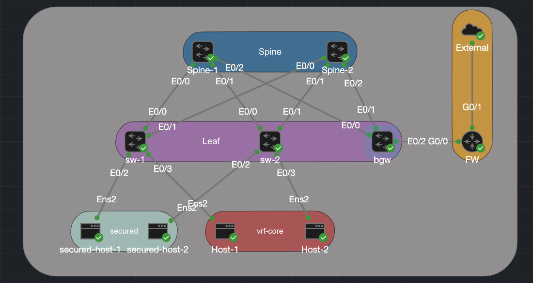
Lab Topology
For this lab I have built a classic spine-leaf topology. Two spines act as BGP route reflectors with no VXLAN awareness of their own, their only job is OSPF underlay reachability and reflecting EVPN routes between leaves. Three leaf switches hang below them, each running a VTEP and hosting the Distributed Anycast Gateway for their locally attached subnets. The hosts are split into two groups. Host-1 and Host-2 sit in internal data subnets (10.0.20.0/24 and 10.0.21.0/24) and use the DAG on their local leaf as their default gateway — traffic between them stays entirely within the fabric and is routed symmetrically via the L3 VNI (Vlan 100). The secured hosts are in a different category: secured-host-1 and secured-host-2 sit in the 192.168.10.0/24 and 192.168.11.0/24 subnets and are not permitted to route freely inside the fabric. Their traffic must pass through the firewall before reaching anything outside their own subnet.
The real action is on the Border Gateway (bgw). This node is where the VXLAN fabric meets the outside world, and it does two distinct things at once. For the routed internal networks it terminates the L3 VNI, holds the VRF core routing table, and runs an eBGP session to the firewall over a dedicated handoff segment (VLAN 900, 10.90.0.0/30) — routes learned from the firewall are redistributed into VRF core and propagated to every leaf as EVPN Type-5 prefixes. For the secured L2 networks it extends the VXLAN-backed VLANs (10 and 11) across a dot1q trunk to the firewall, so those hosts appear as local Layer 2 adjacencies on the firewall’s interfaces rather than routed destinations.
| Device | Loopback1 | Loopback100 | VLANs / VNIs |
|---|---|---|---|
| sw-1 | 10.1.255.3 | 10.100.255.3 | VLAN 10 → VNI 10010, VLAN 20 → VNI 10020, VLAN 100 → VNI 10100 (L3) |
| sw-2 | 10.1.255.4 | 10.100.255.4 | VLAN 11 → VNI 10011, VLAN 21 → VNI 10021, VLAN 100 → VNI 10100 (L3) |
| bgw | 10.1.255.5 | 10.100.255.5 | All of the above + VLAN 900 → VNI 10900 (core handoff) |
| Spine-1 | 10.1.255.1 | 10.100.255.1 | Route reflector only |
| Spine-2 | 10.1.255.2 | 10.100.255.2 | Route reflector only |
| fw | n/a | n/a | g0/0.900 (core handoff) g0/0.10 and g0/0.11 (secured gateway) |
| Host | IP | VLAN | Attached to |
|---|---|---|---|
| secured-host-1 | 192.168.10.5/24 | 10 | sw-1 |
| secured-host-2 | 192.168.11.5/24 | 11 | sw-2 |
| Host-1 | 10.0.20.5/24 | 20 | sw-1 |
| Host-2 | 10.0.21.5/24 | 21 | sw-2 |
The Interfaces
I have covered in my other post how to set up VXLAN, both l2 and l3 so I dont want to go over that again. If you would like to brush up on that you can visit Intergrated Routing And Bridgeing In L3vxlan and Sysmmetric Irb Anycast Gateway On Catalyst.
We have 2 sperate reachability methods that are going on over a simple switchport trunk. There is a routed vlan 900 that carries all the Internet traffic and then there are stretch vlans for the secured host that must go through the firewall. The link between the BGW and the firewall is very simple. On the BGW side it is a simple trunk and then on the Firewall side it is routed sub interfaces. Reaching back to my time doing the CCNA this is called “Router on a stick.” I am just using a router with ACL as a Firefwall for this example. Here we have the 2 protected Vlans, 10 and 11 that terminate on the firewall/router and then vlan 900 which is the routed network that carries all the internal traffic.
BGW
interface Ethernet0/2
 switchport trunk encapsulation dot1q
 switchport mode trunk
FW
interface GigabitEthernet0/0.10
 encapsulation dot1Q 10
 ip address 192.168.10.1 255.255.255.0
 ip access-group secured in
 ip nat inside
!
interface GigabitEthernet0/0.11
 encapsulation dot1Q 11
 ip address 192.168.11.1 255.255.255.0
 ip access-group secured in
 ip nat inside
!
interface GigabitEthernet0/0.900
 encapsulation dot1Q 900
 ip address 10.90.0.2 255.255.255.252
 ip nat inside
L3 Handoff — VLAN 900 SVI and eBGP
VLAN 900 is a small /30 point-to-point segment between bgw and the firewall. It lives inside VRF core so the eBGP session runs entirely within the tenant routing domain and never touches the global table. Here is the configuration of the VRF and the interface vlan 900. Remember that we need to use the keyword stitching to export and import our routes into evpn on the ios xe platform. no autostate ensures the SVI stays up even if no physical ports are active in VLAN 900.
vrf definition core
 rd 65001:5
 !
 address-family ipv4
  route-target export 65001:1
  route-target import 65001:1
  route-target export 65001:1 stitching
  route-target import 65001:1 stitching
interface Vlan900
 vrf forwarding core
 ip address 10.90.0.1 255.255.255.252
 no autostate
The eBGP Session
The eBGP session on the BGW is configured under the VRF core address family so routes learned from the firewall are installed directly into VRF core and immediately redistributable as EVPN Type-5 to the rest of the fabric. The Firewall BGP seesion is very simple, we have a single neighbor and our advertising a default route down into the vxlan fabric. One thing worth noting here. The advertise l2vpn evpn line is what causes routes learned from the firewall to be re-advertised into the EVPN control plane as Type-5 prefixes — without it, those routes would be locally installed on bgw but invisible to the rest of the fabric.
BGW
router bgp 65001
 !
 address-family ipv4 vrf core
  advertise l2vpn evpn
  network 10.90.0.0 mask 255.255.255.252
  neighbor 10.90.0.2 remote-as 65002
  neighbor 10.90.0.2 activate
 exit-address-family
FW
router bgp 65002
 bgp log-neighbor-changes
 network 0.0.0.0
 neighbor 10.90.0.1 remote-as 65001
VLAN-to-VNI Mapping for VLAN 900
VLAN 900 also needs a VNI so it can be carried across the fabric if needed:
l2vpn evpn instance 5 vlan-based
 encapsulation vxlan

vlan configuration 900
 member evpn-instance 5 vni 10900
And the NVE interface includes it:
interface nve1
 member vni 10900 ingress-replication
L2 Extension — Secured VLANs on the Trunk
For the secured hosts, no SVI or routing is configured on bgw for VLANs 10 and 11. The VLANs are simply extended from the VXLAN fabric across the trunk to the firewall. The firewall itself holds the SVIs for 192.168.10.1 and 192.168.11.1 and acts as the gateway.
On bgw, the EVPN instances for VLANs 10 and 11 are configured normally (the fabric still needs to carry MAC/IP reachability for those hosts), but there are no local SVIs routing traffic for those subnets:
l2vpn evpn instance 3 vlan-based
 encapsulation vxlan
!
l2vpn evpn instance 4 vlan-based
 encapsulation vxlan
!
vlan configuration 10
 member evpn-instance 3 vni 10010
!
vlan configuration 11
 member evpn-instance 4 vni 10011
When a secured host sends traffic, it arrives at the leaf (sw-1 or sw-2) via VXLAN, gets forwarded to bgw as a bridged L2 frame, and exits the trunk on the appropriate VLAN toward the firewall. The firewall routes it, applies policy, and sends it onward. There is no symmetric IRB path for these hosts, the firewall is the single choke point by design.
Traffic Flow Walkthrough
Routed traffic — Host-1 to an external destination
- Host-1 (
10.0.20.5) sends a packet to an external IP. Its gateway is the DAG on sw-1 (10.0.20.1). - sw-1 routes within VRF
core. It has a default route learned from bgw via EVPN Type-5, with bgw’s VTEP as the next-hop. - sw-1 encapsulates in VXLAN using the L3 VNI (10100) and sends it to bgw.
- bgw decapsulates, looks up the destination in VRF
core, and finds the route points to10.90.0.2via Vlan900. - bgw sends the packet out the trunk on VLAN 900 to the firewall, which applies policy and forwards externally.
Protected traffic — secured-host-1 to an external destination
secured-host-1(192.168.10.5) sends a packet. Its gateway is the firewall’s interface on VLAN 10 (192.168.10.1).- The frame is bridged — not routed — across the fabric via VXLAN using the L2 VNI (10010) to bgw.
- bgw forwards the frame out the trunk on VLAN 10 directly to the firewall.
- The firewall routes and applies policy. No fabric routing is involved.
Verification
Lets try to ping from 1 of the secured host to the internal network 10.0.20.1, I have place an ACL on the FW that should block this traffic and that is what we see.
On the Host
cisco@secured-host1:~$  ping 10.0.20.1
PING 10.0.20.1 (10.0.20.1) 56(84) bytes of data.
From 192.168.10.1 icmp_seq=1 Packet filtered
From 192.168.10.1 icmp_seq=2 Packet filtered
From 192.168.10.1 icmp_seq=3 Packet filtered
On the FW
Apr 25 18:15:44.529: %SEC-6-IPACCESSLOGDP: list secured denied icmp 192.168.10.5 -> 10.0.20.1 (0/0), 1 packet
However, the secured host can reach the internet.
cisco@secured-host1:~$ ping 8.8.8.8
PING 8.8.8.8 (8.8.8.8) 56(84) bytes of data.
64 bytes from 8.8.8.8: icmp_seq=1 ttl=117 time=14.6 ms
64 bytes from 8.8.8.8: icmp_seq=2 ttl=117 time=12.5 ms
64 bytes from 8.8.8.8: icmp_seq=3 ttl=117 time=11.5 ms
64 bytes from 8.8.8.8: icmp_seq=4 ttl=117 time=11.8 ms
Download
The CML lab file is available in the CML-Labs repository as External_Connections_VXLAN_L2.yaml. Import it directly into CML and bring up the topology — configurations are pre-loaded on all nodes. Please note that for some unknown reason you have to shut and no shut interface vlan 100 (L3 Transit) to get routing to work.